 By
·
11 minute read
By
·
11 minute read
MSTP (Multiple Spanning Tree Protocol) is the IEEE 802.1s standard, now folded into 802.1Q-2005, that groups VLANs into instances so a single switch runs a handful of spanning-tree calculations instead of one per VLAN. It supports up to 65 instances theoretically (16 on Cisco IOS), converges in under a second, and uses a single BPDU carrying M-records to signal every instance at once.
There's a specific moment in every network engineer's career when someone asks "how many VLANs do we have?" and the answer is somewhere between "too many" and "I genuinely have no idea, but I know we created one called VLAN73_TEMP in 2019 and it's definitely still in production".
If you're still running PVST+ (Per-VLAN Spanning Tree Plus) with 40+ VLANs, each running its own spanning tree instance, your distribution switches are working way harder than they need to. Their CPUs have opinions about this, and those opinions involve high utilization and occasional stability issues you'd really rather not experience during peak hours.
MSTP (Multiple Spanning Tree Protocol) solves this by grouping VLANs into regions and instances, so you're running 3-4 spanning tree calculations instead of 47. That's the theory. In practice, MSTP configuration has enough moving parts like region names that must match exactly (yes, including that trailing space you didn't mean to add), revision numbers, instance mappings, that testing it before deployment isn't optional. It's survival.
In Lab 1-1, we validated STP and RSTP convergence behavior. Now we're scaling up to MSTP to see how multi-instance spanning tree actually behaves when you divide your VLANs across multiple regions and instances. Because reading the RFC is one thing; watching it work (or not work) is another.
EVE-NG solves half that problem by letting you build enterprise-grade network labs in software. CloudMyLab solves the other half by hosting those labs so you don't have to hear your cooling fans scream.
CloudmyLab is EVE-NG's official and only cloud partner.

Here's a how to using a ready-made network topology from EVE-NG's Lab Library, hosted where it belongs: in the cloud.
Table of contents:
- What this lab demonstrates
- Topology overview
- Configuration workflow
- Why hosted matters for MSTP testing
- Who needs this lab
- See it running
What this lab demonstrates
Lab 1-2 from EVE-NG's Switching series builds on the STP/RSTP foundation from Lab 1-1 and introduces MSTP with multiple regions and instances. You'll configure MST regions, map VLANs to instances, and observe how the Internal Spanning Tree (IST) coordinates with your MST instances to create a stable multi-VLAN topology. (Or, if you misconfigure something, watch how spectacularly it fails, which is honestly just as educational.)
Here's what you're actually testing:
- MST region configuration: How region names, revision numbers, and instance-to-VLAN mappings define your MSTP boundaries. This is where you'll learn that "CAMPUS" and "Campus" are not the same region, and that trailing spaces count. (Whoever decided region names should be case-sensitive and whitespace-sensitive clearly never had to troubleshoot this at 3 AM.)
- Instance mapping: Assigning VLANs to specific MST instances so you can load-balance traffic across uplinks instead of blocking half your available bandwidth because that's what PVST+ does
- IST vs. MST instances: Understanding the difference between Instance 0 (the Internal Spanning Tree that handles inter-region coordination and that everyone sees) and your custom instances (Instance 1, 2, etc.) that only matter within your region
- Inter-region vs. intra-region behavior: What happens when your MST regions interact at the boundaries, and how your carefully crafted multi-instance design appears as simple CST (Common Spanning Tree) to switches outside your region which is both clever and occasionally frustrating
- Convergence performance: Measuring how MSTP compares to running PVST+ with dozens of individual spanning tree instances burning CPU cycles
Teams run this lab before campus-wide MSTP migrations to verify their instance design actually works as intended. Because discovering that your region configuration has a typo and half your switches are in Region "CAMPUS" while the other half are in Region "CAMPUS " (note the trailing space you added while copying config from a Word document) is way better to learn in a lab than during a maintenance window with your CIO watching.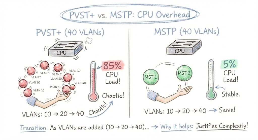
STP, RSTP, PVST+, and MSTP at a glance
Before diving into MSTP-specific configuration, here is how the four spanning tree variants compare on the dimensions that matter operationally:
| Protocol | Standard | Convergence | BPDU model | Spanning-tree instances | Best for |
|---|---|---|---|---|---|
| STP | IEEE 802.1D | 30-50 sec | One per network | 1 | Legacy networks, simplicity |
| RSTP | IEEE 802.1w | Sub-second | One per network | 1 | Modern small/mid networks |
| PVST+ / Rapid-PVST+ | Cisco proprietary | 30-50 sec / sub-second | One per VLAN | 1 per VLAN (40 VLANs = 40 instances) | Cisco-only with low VLAN counts |
| MSTP | IEEE 802.1s / 802.1Q-2005 | Sub-second | Single BPDU with M-records | Up to 65 (16 Cisco) | Large networks, 30+ VLANs |
If you are managing a campus with 30+ VLANs, MSTP is the only option that scales without melting distribution-switch CPUs. CloudMyLab's hosted EVE-NG gives teams a pre-built distribution/access topology to validate the migration before touching production, no hardware required.
Topology overview
The topology for Lab 1-2 extends the basic distribution/access design from Lab 1-1 but adds VLAN diversity and regional boundaries to make things interesting. It's still from EVE-NG's Lab Library, which means you're not building this from scratch while trying to remember which VLAN numbers you used for which purpose back in 2018.
Core components:
- DS-1 and DS-2: Distribution switches that will anchor your MST regions (Cisco IOSvL2, same as Lab 1-1)
- AS-1 and AS-2: Access switches participating in the same MST region
- Multiple VLANs: Typically VLAN 10, 20, 30, 40+ to demonstrate instance grouping. That is enough to make the lab interesting without creating a VLAN management nightmare
- Optional additional region: Sometimes includes switches configured in a second MST region to test inter-region behavior and prove that your understanding of CST boundaries is solid
Key MST configuration elements:
- Region name: Must match exactly across all switches in the region, including spaces, capitalization, and any stray characters you accidentally pasted from your notes
- Revision number: Typically starts at 1; must match within region (increment it when you change VLAN-to-instance mappings, or face confusion)
- Instance mapping: Which VLANs belong to which MST instances (e.g., VLANs 10-20 → Instance 1, VLANs 30-40 → Instance 2)
- Root bridge per instance: You'll configure different distribution switches as root for different instances to load-balance traffic instead of sending everything through one switch
Topology adapted from the EVE-NG Lab Library.
This design mirrors what you'd see in a real campus deployment where you're dividing VLANs into logical groups (maybe by department), building, or just "these VLANs probably belong together based on that network diagram we found from 2015" and mapping them to spanning tree instances. The goal is to prove you can manage 40 VLANs with 3 MST instances instead of 40 PVST+ instances slowly consuming your switches' CPU cycles.
Configuration workflow
This workflow assumes you've completed Lab 1-1 or at least understand basic spanning tree concepts. If you're using CloudMyLab's hosted EVE-NG, the topology is pre-loaded and typically takes 60-90 minutes to configure and test fully.
Establish baseline with PVST+ or RSTP
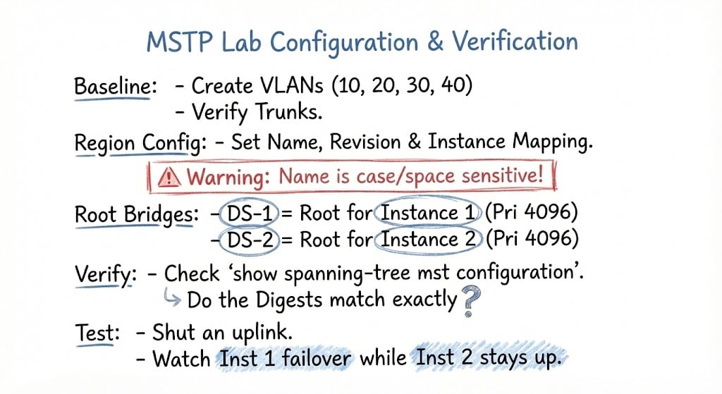
Start by configuring your topology with either PVST+ or Rapid-PVST to establish a baseline. Create your VLANs (10, 20, 30, 40), configure trunk links, and verify that spanning tree is working for all VLANs. If you completed Lab 1-1, this should feel familiar.
Run show spanning-tree on each switch and note how many spanning tree instances you're running. If you've got 4 VLANs, you're running 4 separate spanning tree calculations, one per VLAN. Scale that to 40 VLANs, and you can see why this becomes problematic. Your distribution switches are recalculating topology for every VLAN independently, which is technically correct but operationally wasteful.
Document your CPU utilization with show processes cpu | include Spanning so you have a before/after comparison. On a small 4-VLAN lab, the CPU impact won't be dramatic, but knowing the baseline helps you understand what changes when you migrate to MSTP.
Configure MST region parameters
This is where MSTP configuration gets specific and unforgiving. On all switches that should participate in the same MST region, you'll enter global configuration mode and define your MST parameters:
spanning-tree mode mst
spanning-tree mst configuration
name CAMPUS
revision 1
instance 1 vlan 10,20
instance 2 vlan 30,40
exit
Three attributes must match exactly across every switch that should belong to the same region: the region name, the revision number (default 0, but most labs start at 1), and the instance-to-VLAN mapping. Miss any one of them and the switches treat each other as CST boundaries. The match check is case-sensitive and whitespace-sensitive every-character-matters exactly. If DS-1 has name CAMPUS and DS-2 has name Campus, they're in different regions. (Yes, this is case-sensitive. Yes, I've spent multiple hours troubleshooting this exact issue. Yes, I'm still bitter about it.)
The default max hop count inside a region is 20, decremented by each switch as the BPDU traverses the topology. That's your safety net against routing loops if something corrupts the topology calculation.
Verify region consistency with show spanning-tree mst configuration. The output includes a configuration digest basically a hash of your MST settings. If the digest doesn't match across switches, you have a mismatch somewhere. Find it before you move on, because proceeding with mismatched regions leads to topology behavior that will make you question your understanding of spanning tree fundamentals.
Configure root bridges per instance
Unlike PVST+ where you typically set one root bridge for everything (and accept that half your uplink bandwidth sits idle in blocking state), MSTP lets you load-balance by making different switches root for different instances:
! On DS-1:
spanning-tree mst 1 priority 4096

! On DS-2:
spanning-tree mst 2 priority 4096
Now VLANs 10 and 20 (Instance 1) will prefer paths through DS-1, while VLANs 30 and 40 (Instance 2) prefer paths through DS-2. This distributes your traffic across both distribution switches instead of sending everything through one switch while the other switch sits there with perfectly good uplinks doing nothing.
Verify with show spanning-tree mst and check which switch is root for each instance. You should see DS-1 as root for Instance 1 and DS-2 as root for Instance 2. If you're seeing the same switch as root for both instances, go back and check your priority configurations. You probably typo'd something.
Test instance isolation and convergence
Now for the interesting part: breaking things on purpose to see how MSTP handles failures. Shut down the uplink from AS-1 to DS-1 and observe which VLANs fail over and which don't.
VLANs 10 and 20 (Instance 1, rooted at DS-1) should reconverge quickly to use the path through DS-2 instead. VLANs 30 and 40 (Instance 2, rooted at DS-2) might not be affected at all since their primary path is still intact. This is MSTP's superpower: a failure can affect some VLANs without disrupting others, depending on your instance design and root placement.
Time the convergence with a continuous ping from a PC in VLAN 10. You should see RSTP-like convergence speeds (sub-second to a few seconds) rather than classic STP's 30-50 second reconvergence. If you're seeing 30+ second outages, something's wrong. Check whether you actually enabled MST mode on all switches or whether some are still running PVST+.
Optionally test inter-region behavior
If your topology includes a second MST region, verify how the regions interact. From the perspective of the other region, your entire MST region appears as a single CST (Common Spanning Tree) entity. This means inter-region links will show different behavior than intra-region links.
Use show spanning-tree mst at the boundary switches and note the "boundary" designation on ports connecting to different regions. Document how IST (Instance 0) handles inter-region coordination.
Compare resource utilization
Go back to your baseline CPU measurements from step 1 and check again with show processes cpu | include Spanning. You should see lower CPU utilization with MSTP because you're running 2-3 instance calculations instead of 4 PVST+ calculations (or 40, if you're testing at realistic scale).
On a 4-VLAN lab topology, this difference won't be dramatic. Probably 1-2% CPU difference. But the math scales linearly: if you're running 40 VLANs in production, that's 40 PVST+ instance calculations vs. maybe 4 MSTP instance calculations. The CPU savings become real.
Document this for your business justification when your manager asks why you want to spend time migrating to MSTP. "Because our distribution switches are at 18% CPU utilization under normal load and I'd like that to be 6%" is a compelling argument, especially when paired with improved convergence behavior.
Document your instance design
Capture your final MST configuration, including region name, revision, instance-to-VLAN mappings, and root bridge assignments per instance. Note which VLANs use which uplinks and how traffic is load-balanced across your distribution layer.
The point isn't just to get it working; it's to understand why it works so you can troubleshoot when someone inevitably adds a switch to the wrong MST region at 2 AM and wonders why nothing is working.
Why hosted matters for MSTP testing
MSTP configuration is finicky enough that you really don't want to discover issues in production. Region mismatches, instance mapping errors, and root bridge placement problems can cause traffic to take unexpected paths or cause instability.
Testing MSTP locally means managing multiple VLANs, running CPU-intensive spanning tree calculations, and probably hitting resource constraints on your laptop before you finish the lab.
CloudMyLab's hosted EVE-NG removes those constraints (See Lab 1-1 STP & RSTP on EVE-NG for the full breakdown of hosted benefits, zero local setup, multi-user sessions, repeatable snapshots, expandable scope).
For MSTP specifically, hosted environments are valuable because:
Configuration iteration is faster: Made a typo in your region name? Revert to snapshot, fix it, test again. No 20-minute rebuild process.
You can test at realistic scale: Want to see how 30+ VLANs across 5 MST instances actually performs? Do it without melting your laptop's CPU.
Team validation is easier: MSTP designs need peer review because the configuration has so many interdependencies. Having your team connect simultaneously to verify region configs match is way more effective than screenshot reviews.
Who needs this lab
MSTP isn't for everyone. If you're running 5 VLANs on a small network with two distribution switches, PVST+ or Rapid-PVST works fine and you probably don't need the additional complexity. But MSTP becomes critical once your VLAN count starts approaching "how did we end up with this many?" territory.
- Large campus networks with 30+ VLANs need MSTP to reduce spanning tree overhead and improve switch CPU utilization. If your distribution switches are showing concerning CPU utilization from spanning tree processes, this lab proves whether MSTP solves the problem or whether you actually have a different issue that MSTP won't fix.
- Multi-building enterprises use MST regions to create spanning tree boundaries at logical locations (per building, per distribution block, or per geographic area). This lab validates that your regional design works before you deploy it across 20 buildings and discover that Building 3's switches think they're in a different region than everyone else because someone copied the config from a Word document with smart quotes enabled.
- MSPs managing multi-tenant environments leverage MSTP to create isolated spanning tree domains while maintaining overall stability. If you're running separate VLAN ranges per tenant, grouping those into dedicated MST instances makes operational sense. (And yes, Private VLANs (Lab 1-6) often pair with MSTP for complete tenant isolation.)
- Network engineers preparing for CCNP ENCOR will recognize this as exam-critical content. You need to understand MSTP region configuration, instance mapping, and IST behavior to pass. But more importantly, this is the kind of thing you need to understand deeply before you're responsible for a production campus network where "oops, I misconfigured the region name" means a building full of people can't work. The exam tests whether you can configure it correctly once; production tests whether you can troubleshoot it at 3 AM when something inevitably goes wrong.
See it running
Want to validate your MSTP design before deploying it across your campus network, and potentially discovering region configuration mismatches in production?
We'll provision Lab 1-2 from EVE-NG's Lab Library with your specific VLAN and instance requirements. You'll see exactly how region configuration works (and how easy it is to misconfigure by one misplaced space character), test load-balancing across multiple instances, and measure the CPU utilization improvement compared to PVST+. Most importantly, you'll catch configuration errors in the lab instead of during the maintenance window.
No hardware required. No local resource constraints. No waiting for your laptop to handle 40 VLANs worth of spanning tree calculations. Just working MSTP behavior you can verify, document, and use as a reference when you deploy the real thing.
Frequently asked questions
What is MSTP in networking?
MSTP (Multiple Spanning Tree Protocol) is the IEEE 802.1s standard, now part of 802.1Q-2005, that groups VLANs into instances so a switch runs a handful of spanning-tree calculations instead of one per VLAN. It supports up to 65 instances theoretically (16 on Cisco IOS), converges in under a second, and uses a single BPDU carrying M-records to signal every instance at once.
What is the difference between STP, RSTP, and MSTP?
STP (802.1D) runs one spanning tree for the whole network and converges in 30-50 seconds. RSTP (802.1w) keeps the single-tree model but converges sub-second. MSTP (802.1s) runs multiple instances grouped by VLAN, supports sub-second convergence, and scales to 65 instances theoretically (16 Cisco-supported).
What is an MSTP region?
An MSTP region is a group of switches that share the same region name, revision number, and instance-to-VLAN mapping. Switches inside the region run multiple spanning-tree instances. To other regions or non-MSTP switches, the entire region appears as a single CST (Common Spanning Tree) entity.
What three MSTP attributes must match for switches to be in the same region?
Region name, revision number, and instance-to-VLAN mapping. All three must match exactly across switches. The check is case-sensitive and whitespace-sensitive. The configuration digest (visible via show spanning-tree mst configuration) is a hash of these values; matching digests confirm region membership.
How many MSTP instances can you configure?
The IEEE 802.1s standard supports up to 65 instances (Instance 0 plus 1-64). Cisco IOS supports 16 instances in practice. Most production deployments use 2-4 instances, which is enough to load-balance across redundant uplinks without unnecessary configuration overhead.
What is Instance 0 in MSTP?
Instance 0, also called the IST (Internal Spanning Tree) or CIST (Common and Internal Spanning Tree), is the default instance every MSTP switch participates in. It coordinates between MST regions and handles all VLANs not explicitly mapped to a custom instance. It is also what non-MSTP switches at region boundaries see.
How does MSTP achieve load balancing?
Configure different distribution switches as root bridge for different MST instances. VLANs in Instance 1 will prefer paths through one switch, while VLANs in Instance 2 prefer paths through the other. Both uplinks carry traffic instead of one blocking, with sub-second failover if either path goes down.
Is MSTP backward compatible with 802.1D STP?
Yes. MSTP regions interoperate with legacy 802.1D STP and 802.1w RSTP switches at boundary ports. The MSTP region appears as a single virtual switch running CST to non-MSTP neighbors, so you can migrate switches into the region incrementally without disrupting the rest of the network.
